PCM1798 + 6N16B
This is the most fully developed future build in the archive: a Lampucera-style PCM1798 DAC feeding a MELZ 6N16B-V SRPP stage that also acts as a line preamp, with fixed/variable output and a separately designed high-voltage supply.
Modern conversion, deliberately analogue control.
The project grew out of the first MikroLampizator, but it is not simply a larger version of that CD-player modification.
The PCM1798 branch is intended to separate responsibilities more clearly. The DAC board performs conversion. The 6N16B stage handles I/V and analogue gain in the working topology, can also accept line-level sources, and provides the system volume stage when required. That makes it a DAC and a control centre rather than a single-purpose output buffer.
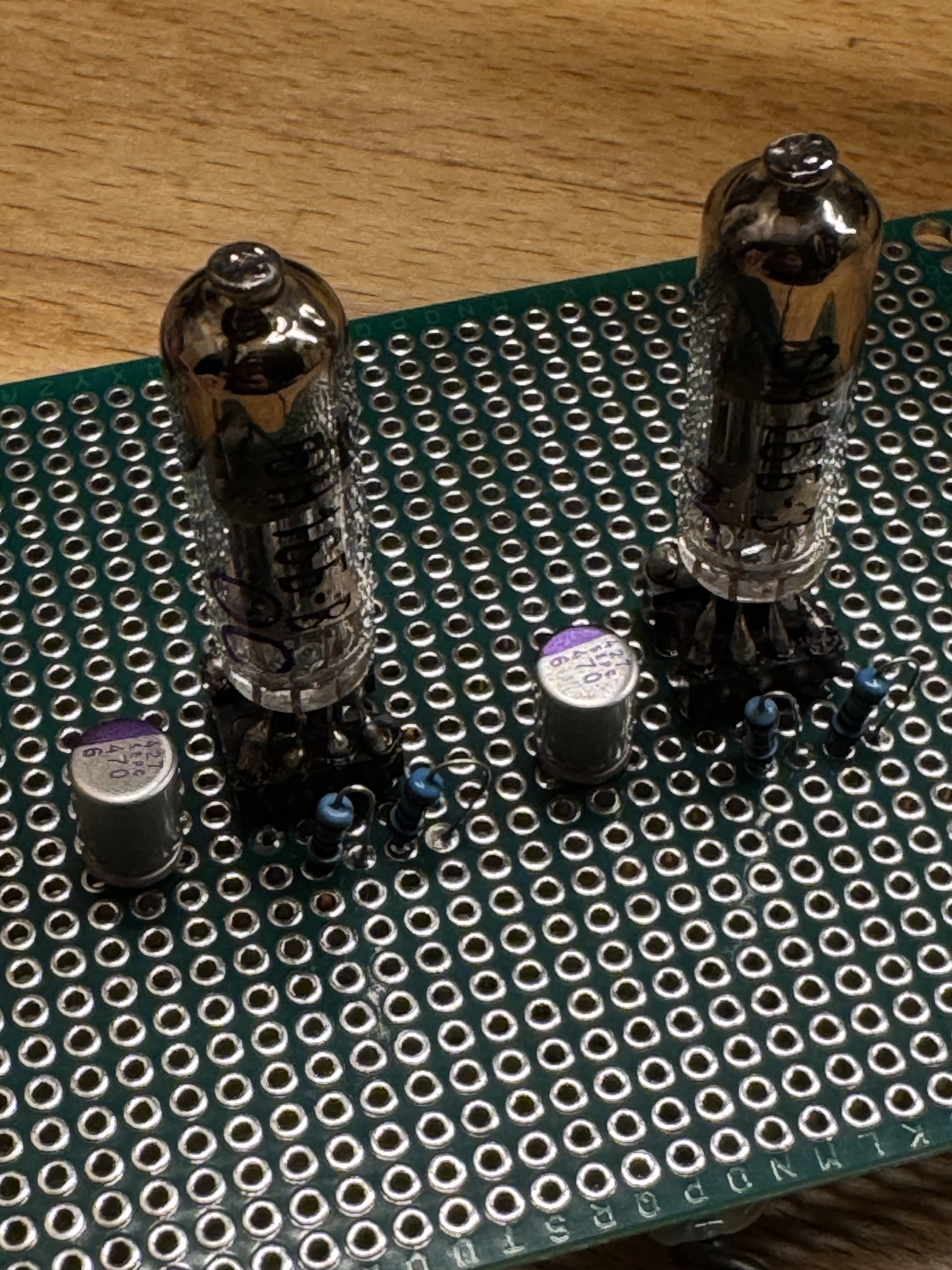
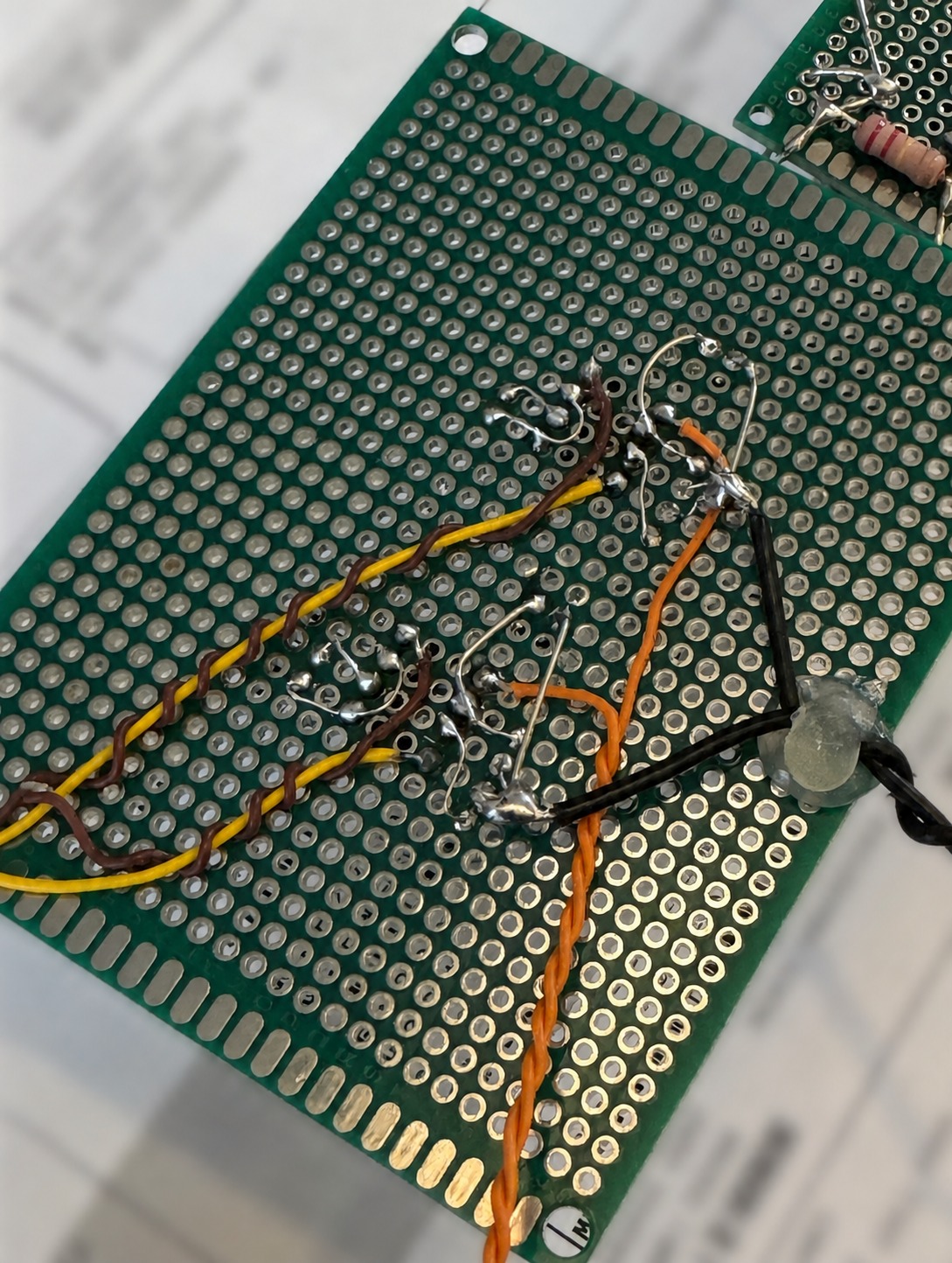
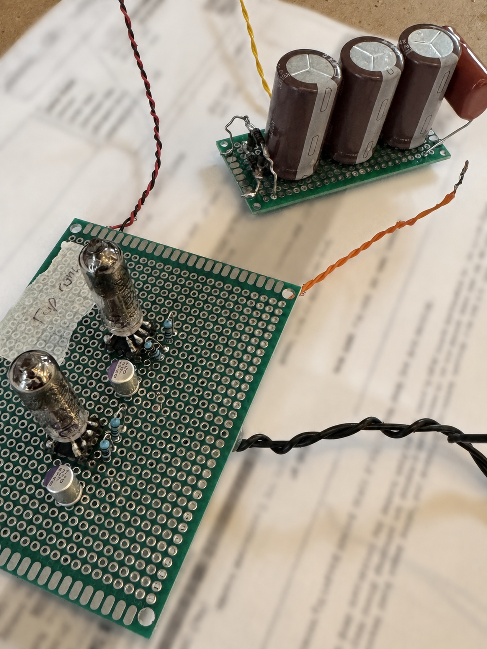
The photograph shows real 6N16B valve-stage and supply development hardware from the project archive. It does not imply that the complete PCM1798 DAC/preamp has already been assembled.
The February 2025 planning document already identified the architectural goal: build variable output from the beginning so a separate power amplifier can be used without buying an integrated amplifier and then redesigning the system later.
One SRPP stage, two kinds of input, two output modes.
The switching notes use 620 Ω to ground on the DAC position, combining I/V and grid reference in the working Lampizator-style topology.
Line-level inputs use 300 kΩ to ground so the SRPP can operate as a conventional preamp stage rather than as a DAC I/V load.
A 1 MΩ reference on the selector common is retained in the later notes so the grid does not float while contacts move between positions.
The design allows the 100 kΩ logarithmic attenuator to be bypassed, preserving a direct fixed path when another downstream control stage is preferred.
The archive contains several switching iterations, from simple DAC/line selection to three line inputs plus DAC. The current public description preserves the common architecture rather than pretending the physical front-panel layout is already final.
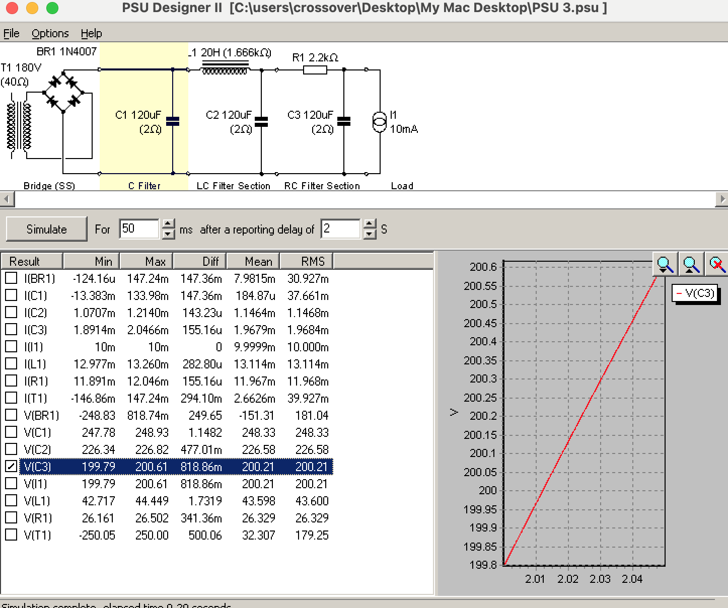
The later notes converge on roughly 220 V B+ through C-L-C-R-C filtering.
The power supply received unusually deep attention because this build is intended to make the valve stage the system control centre. The important point is the progression from a general “good valve PSU” idea to a component-level model that can be tested under load.
Later modelling centres on roughly 217–222 V at the SRPP node, around 7 mA total load. Actual mains voltage and tube current will decide the final resistor value.
750 Ω is the later reference value, with the design notes estimating roughly 6.6–7 mA total and a balanced operating point rather than maximum gain.
The later power document selects a 0.68 µF Panasonic ECW-F / 630 V polypropylene part across C3, replacing an earlier X2-cap idea for this DC role.
A 6.3 V AC heater winding is retained in the plan. The notes also preserve a 1 µF X2 heater-to-ground decoupling element as a build-specific hum-control experiment to be verified in practice.
Two 220 kΩ / 2 W bleeders are placed around the first two reservoir nodes in the later plan for controlled discharge and safer servicing.
The PCM1798 board remains electrically separate, with a dedicated low-voltage transformer/supply path rather than sharing the valve B+ architecture.
The project deliberately stops treating every capacitor as the same kind of “upgrade”.
Keep the Oscons where they already make sense
Later PCM1798 documents conclude that wholesale replacement of the existing low-ESR Oscon decoupling with SEPC is low priority. Digital and op-amp rails need low impedance and stability more than tonal experimentation.
SEPC as a circuit component
The planned 470 µF / 6.3 V SEPC cathode bypass sits inside the SRPP’s bias/gain behaviour. A later film-bypass document explicitly argues against paralleling another film capacitor here simply for “more detail”.
0.5 µF MBM PIO + 0.01 µF CuTF
The planned output network uses the PIO for body and decay, with a small CuTF bypass explored for extension and low-level air. This is a signal-path voicing decision, unlike supply decoupling.
The preferred year changed as the imagined system around the tube changed.
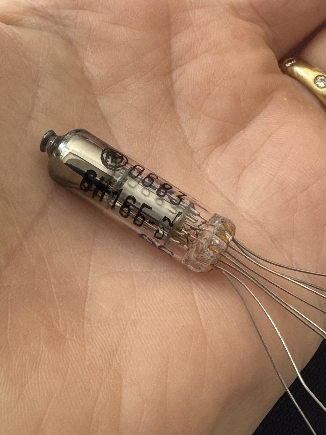
This is a useful example of why the archive preserves intermediate documents. Early comparisons sometimes favoured 1979 or 1988 6N16B-V depending the DAC and desired balance. A later MELZ comparison settled on 1983 as the best all-round match for the PCM1798 project because it sat between warmth and neutrality.
| Research stage | Preference | Reasoning recorded at the time |
|---|---|---|
| Early all-DAC comparison | 1979 MELZ | Balanced, natural and safe across several DAC personalities when paired with PIO/CuTF. |
| Holography-first comparison | 1988 | More neutral, fast and open when the rest of the system already supplies body. |
| Later PCM1798-specific synthesis | 1983 MELZ | Warm-neutral balance, tight bass, organic mids and enough extension without making the PCM1798 branch too analytical. |
These are research preferences, not measured guarantees. The finished build will need real tube comparisons because transformer behaviour, actual B+, coupling caps, amplifier input impedance and P17 placement will all change the result.
The final authority will be the listening diary, not the design document.
Does the supply land where the model predicts?
Measure B+ under load, heater voltage, hum, current draw, temperature and the real drop across choke/resistor before treating any simulated sweet spot as final.
Do DAC and line modes switch silently and safely?
Confirm the grid never floats, that the attenuator presents sensible loading and that fixed/variable modes do not introduce level or channel-matching problems.
Is 0.5 µF right for the real amplifier load?
Coupling value only makes sense against actual input impedance. The intended power stage must be part of the verification.
Does 1983 MELZ remain the right choice?
Compare against the 1988 and other available variants only after the circuit is stable. The tube should not be chosen to repair a problem elsewhere.
Does it add something the D30/Mikro do not?
The project earns a place only if its modern-converter/valve-control combination adds a distinct, useful perspective rather than duplicating an existing reference.
Does attention move away from the circuit?
The same P17 test applies: if the system becomes more impressive but the piece of music becomes less absorbing, the design has missed its own brief.
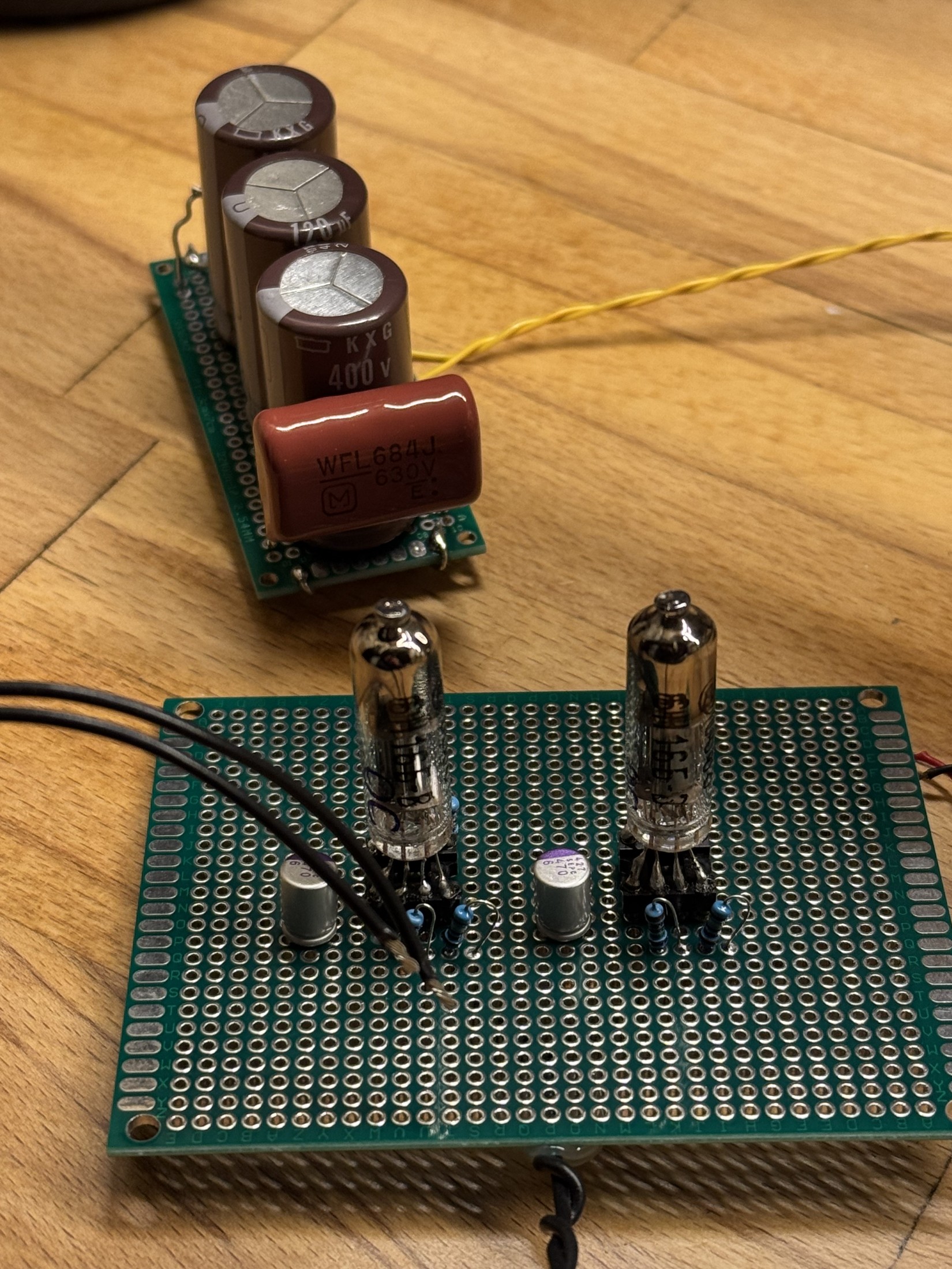
A separate development photograph showing the 6N16B stage and prototype supply. This is not the completed PCM1798 DAC/preamp.
The archive has already moved beyond a purely imaginary schematic.
Parts, tube stock, prototype boards and PSU modelling exist, but the complete PCM1798 + 6N16B DAC/preamp has not been assembled and validated as the reference design described on this page.
This distinction is important. The physical archive can illustrate the development without allowing a visitor to mistake a prototype or parts layout for a finished product.
The physical build record is wider than a single prototype photograph.
The archive includes the valve-stage board, supply board, tube close-ups, underside wiring and PSU modelling. Together they show the project moving from topology and component selection towards something that can eventually be assembled and measured as a complete DAC/preamp.