A capacitor has a job before it has a reputation.
The archive explores PIO, V-Cap ODAM, CuTF, ClarityCap and other options across valve output stages and the P17 crossover. The electrical role is kept separate from the subjective voicing hypothesis.
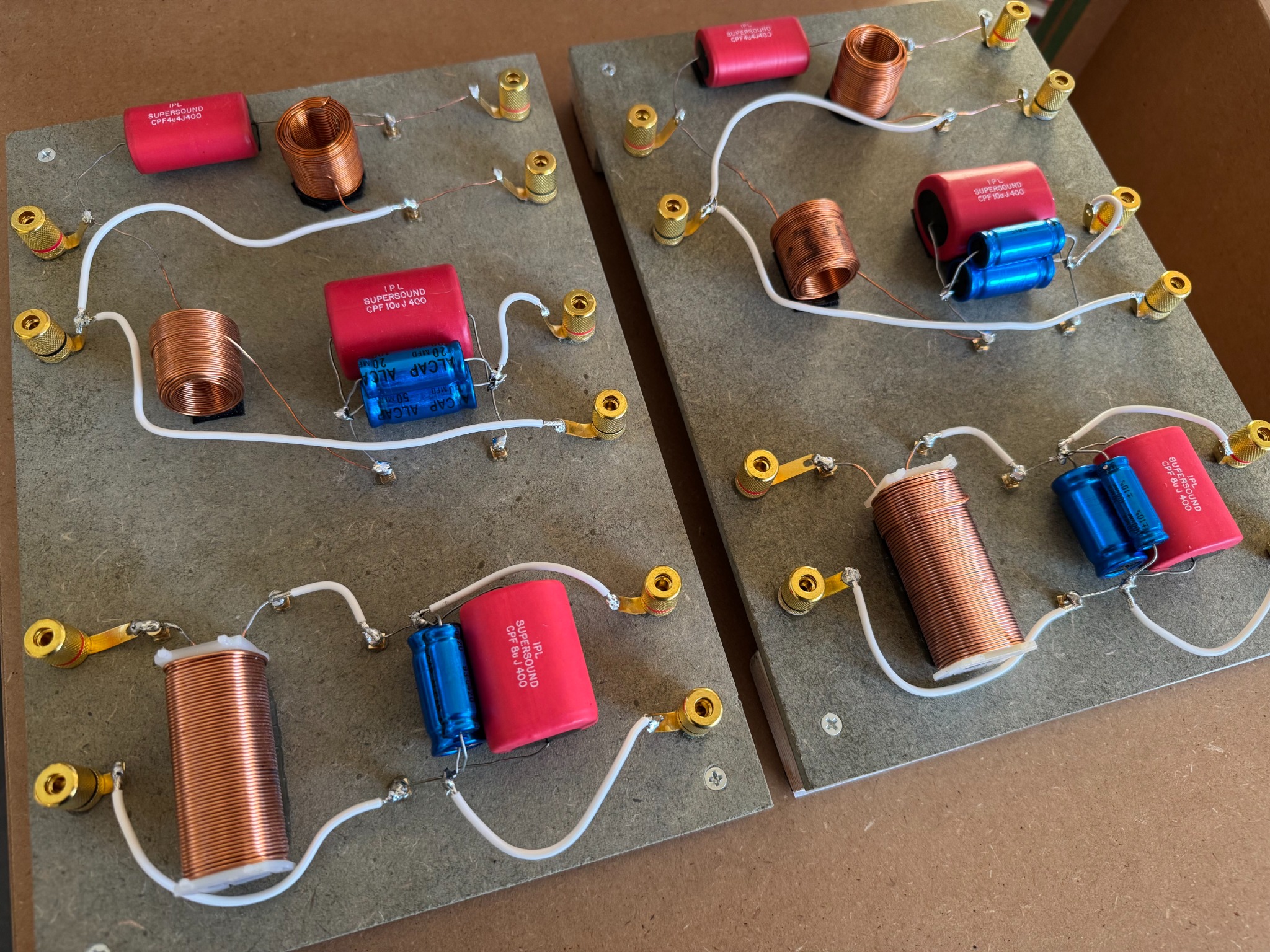
Four stages, one increasingly selective philosophy.
The P17 archive is most useful when the stages are kept separate: the network that was actually heard, the Lampizator-inspired premium allocation, the full-V-Cap cost-no-object exploration, and the later optimised route that deliberately does not use the most expensive capacitor everywhere.
The principle is not “put the most expensive capacitor everywhere”. The notes repeatedly prioritise the exposed mid and high-frequency paths, while treating the bass section more pragmatically around correct value, low loss and electrical suitability.
The full capacitor picture.
These are development directions recorded after the reference P17 was built. They describe what could be explored in a future network, not what is fitted to the completed reference pair.
4 µF ODAM + 0.1 µF CuTF
The most ambitious path is around the 10 cm SABA high-frequency driver: a 4 µF V-Cap ODAM with a 0.1 µF CuTF bypass. The aim is to preserve paper-cone body while exploring greater air, microtexture and decay.
20 µF × 4 ODAM
The later notes specify four 20 µF ODAM capacitors for the midrange sections. This reflects the importance placed on vocal density, harmonic completeness and the 20 cm SABA driver’s role through the human centre of the loudspeaker.
2 × 33 µF, selected towards ~68 µF
For the bass network, the notes record two 33 µF capacitors, measured on the higher side to bring the combined value close to 68 µF. Here the design priority is the required electrical value and integration with the 15-inch McKenzie, rather than using exotic parts simply for prestige.
Different architectures, related harmonic priorities.
Later system notes explore using related coupling philosophies across DAC output stages and speaker networks so technically different sources still arrive at a recognisable tonal language.
This is best understood as a voicing strategy rather than a scientific requirement. It can create continuity, but too much of the same character can also become cumulative. Every stage still needs to earn its place by listening.
Three tiers preserve the actual evolution rather than jumping straight to the most expensive idea.
The reference network
- High frequency: 4 µF IPL Supersound film
- Midrange: 70 µF Alcap + 10 µF IPL Supersound
- Bass: 60 µF Alcap + 8 µF IPL Supersound
This is the network against which every later idea must be judged because it is the one that produced the March 2025 “songs feel like stories” listening result.
Targeted premium route
- High frequency: 4 µF ODAM + 0.1 µF CuTF bypass
- Midrange: 80 µF ClarityCap CSA
- Bass: 68 µF Monacor MKP
The February 2025 optimisation documents treat this as a rational full-film step: put the most ambitious parts where they are most exposed, while improving mid/bass dielectric quality without making every position equally extravagant.
Full V-Cap direction
- High frequency: 4 µF ODAM + 0.1 µF CuTF
- Midrange: 4 × 20 µF ODAM
- Bass: 2 × 33 µF ODAM, selected/measured towards ~68 µF combined
Later correspondence and master notes push the same principle to its cost-no-object conclusion. This tier remains unbuilt and should be heard as a separate network, not assumed superior by price.
The same capacitor cannot mean the same thing everywhere.
Value, ESR, driver impedance and acoustic handover dominate. A small CuTF bypass may be used as deliberate voicing on the high-frequency path.
PIO + CuTF is explored as a series coupling combination where dielectric behaviour directly sits in the audio path.
The SEPC research argues against adding a film bypass simply because film is “better”; the polymer already performs a very different circuit job.
The PCM1798 work concludes that existing Oscons are already appropriate low-ESR parts. Wholesale SEPC replacement would spend money where the design gain is least clear.
Why the all-ODAM route was not the final conclusion.
The archive eventually separates maximum possible spend from maximum system sense.
ODAM + CuTF remains the strongest researched choice because the 10 cm SABA is where extra air, decay and fine spatial information can be pursued most directly.
ClarityCap CSA remains the later preferred 80 µF solution. The research judged an all-ODAM 80 µF mid section technically attractive but financially disproportionate to the likely incremental gain.
Monacor MKP at 68 µF becomes the clearest value-led choice. Large bass capacitance should meet electrical and loss requirements without forcing boutique pricing into the least exposed part of the network.
The result is not a budget compromise. It is selective maximalism: spend extravagantly where the circuit role and listening target justify it, and preserve proportion everywhere else.